Stereo vision color calibration

    Last time, I noticed that my webcams didn’t have the same color response. One is white clear, the other is red tinted…
This difference in color is not desirable when trying to apply stereo vision algorithms such as disparity mapping. It requires two images with the same aspect to allow matching algorithm to work best.

    I read an article from Afshin Sepehri called Color Calibration of Stereo Camera that describes in details a technique to deal with this problem.

About the article

    The article details a technique that allows correcting the stereo image couple by applying a mathematical function on each pixel to change their color to a calibrated one, which is the true color.

    He uses random test patterns composed of colored squares which are then printed to be viewed by the webcams to calibrate.

Afshin’s example test pattern

    Then, he has the true color, left viewed color and right viewed color. He applies a minimization algorithm to find the mathematical function to apply on the left and right image pixels to calibrate each image to obtain true and identical colors.

For the minimization process he has to approaches :

    1. Assuming that each true color component only depends on the same component : Rc = f(Rf) , Gc = f(Gf) , Bc = f(Bf)
    2. Assuming that each true color component depend on all the other components : Rc = f 1(Rf, Gf, Bf)   ,   Gc = f2 (Rf, Gf, Bf)   ,   Bc = f3 (Rf, Gf, Bf)

    After testing both, he concludes that the best one is the second one. He shows his results and it seems to be quite interesting !

    I was quite furstrated by the fact that the article does not show the outcome of this technique on the disparity map output to see if it’s really relevant or not… That’s why I decided to give this a try and implement my own color calibration algorithm based on Afshin’s article.

My implementation idea

    My approach is mainly the same than Afshin’s except that I decided to build a relative correcting algorithm whereas Afshin’s algorithm is an absolut one.
He tries to obtain the true colors on his final images which has some issues :

    • After printing the test patterns, there may be some color errors on the colors due to printer color calibration itself
    • Scene lighting and light reflections may change the webcam perception of the color and introduce errors
    • There’s two models, one for each image, so it may require high computing power to run it online in real time

My idea is based on these points :

    • One of the two webcam image is considered the reference, the calibration algorithm will have to correct the other image to be as close as possible from the reference
    • The algorithm does not give the true colors but we have both image colors calibrated

Implementation steps

On the programming part, I had the following points to code :

    • Random test chessboard pattern generator : generate one or more random test patterns as image files to be printed
    • Test pattern finder : algorithm to find and extract the chessboard from an image
    • Color pattern extraction : locate the colored squares and make an average of the pixels it contains. It gives a list of the colors of each square.
    • Minimization process : algorithm to build the model by finding a function to transform the old (uncalibrated) pixel colors to new calibrated pixel colors. It gives a transformation matrix that then can be saved to a file and loaded on another program, same as we do with extrinsics and intrinsics (see previous article)
    • Image transformation algorithm : point an image on the input and take the calibrated image on the output

Final result

Once all these point programmed, it gives a quite interesting result ! Here is a quick preview :

StereoColorCalibrationScreenshot

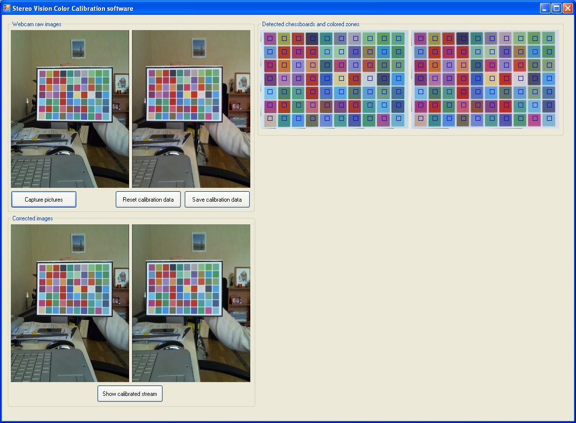
    On the top left, you can see the uncalibrated raw images from the webcams, on the top right, it’s the chessboards extracted from the stereo images.
On the bottom left, you can see the calibrated images output.

    On this sample application, I calibrated the right image using the left image as a reference. So, you can see that the right image before calibration is a little reddish and once it has been processed, it’s clearer and corresponds really well to the one on the left !
Mission cleared !

    Oh, I must mention though, that it runs quite slowly on my computer configuration as all this is running on a virtual machine. The VM runs on my 2007 Dell Inspiron 1520 laptop which begins to lack some processing capacity…
I’m currently considering buying a desktop computer with some « hardcore gamer » features… The problem is that it’s quite expensive… Hard choice !

Stereo matching – first trials

We now have the webcam images, left and right. Let’s apply the stereo matchnig algorithm.

Beforehand

Before doing anything, we first have to calibrate the webcams.
I tried a little without to see what it really does when there’s no calibration : it works, but the results depend on how well you manually turned the webcams to have the images aligned.
It also greatly depends on how good the webcam lens are, since they deform the image. It’s not something you can clearly see by looking at the images.
It’s only once you run the calibration that you can figure out how distorted your images are and that’s quite astonishing !

So what calibration does ?
It runs some image modifications to map the images to a zone on which both images are perfectly planar and aligned.
It may require cropping a little your images because it gives some distorted borders as it applies a deformation algorithm on each image.
As an example, here is the output from the OpenCV stereo_match sample application.

StereoMatch00

Now, we have the assurance that both images we get from this algorithm are well calibrated and perfectly aligned. It makes a big difference on the resulting disparity map.

My implementation idea

As I explained, I need my webcams to be calibrated.
I spent some time searching for how I can do it and the easiest way I could find is using the stereo_calib sample from OpenCV framework.
Unfortunately, EmguCV does not give samples we could play with to calibrate the webcams.
OpenCV has a lot of samples including two apps called stereo_calib and stereo_match which are perfect for what we’d like to do !

The stereo_calib program uses many couples of stereo images of a chessboard to calculate a few matrices that are stored on two files named intrinsics.yml and extrinsics.yml.These files are then used by the final application to calculate the image deformation and then obtain calibrated images.
This part is shown on the stereo_match sample from OpenCV.

On the implementation part, I think it’s better to stay as close of the OpenCV environment as possible.
The idea is to use stereo_calib sample application to calibrate the webcams and generate the YML files.
Then, on my C# program, load these files and compute the image deformations by porting some parts of the stereo_match sample application using EmguCV.
Of course, we could do the same for the stereo_calib sample, port it to C# instead of directly using it from OpenCV… I found this sample quite complete and it does exactly what I required so, I chose not to waste my time on it.

Installing OpenCV

So, as I said before, we have to install OpenCV to access its sample apps.
Since I found it not that easy to do without prior knowledge, I’m about to explain the main steps I went through. If it helps…

You first have to download the latest OpenCV package : http://opencv.org/

Once you got it, install it.
If you don’t have it, download and install CMake : http://www.cmake.org/cmake/resources/software.html

On Windows (probably the same for other OS), open a terminal window, navigate to where you installed OpenCV, navigate to the samples folder and then run Cmake on it. It should build the samples. Be aware that it may take some time to compile…

Once it’s built, you may now have on the Build folder, the OpenCV samples as executables.

Running the calibration

With OpenCV, there’s stereo images called right–.jpg and left–.jpg with — going from 01 to 13. There’s also a file called stereo_calib.xml which contains the image list of these files.
So you can copy these files and paste it to the same directory as the stereo_calib executables. You can now run stereo_calib and see what it gives !

Final result

Ok, it’s working now ! I ran the sample app with my own stereo images and got the extrinsics and intrinsics files which I then loaded into my program and it gives this :

DisparityMap

That’s pretty encouraging ! We can clearly see the shapes of lamp and distinguish the helicopter !

That’s quite good, but I would like to go a bit further in the subject. I noticed that the cameras don’t have the same color rendering, as you can see from the screenshot. Sometimes it’s even worse, depending on how one camera chose to adapt to the surroundings (ambient light, focus and so on). I saw that it can significantly affect the stereo matching results.

So what I’ll try to do is lock some parameters of the camera starting by exposure which keeps on changing the brightness of the image.
I’m also about to try some color calibration algorithms.
I’ll then be able to see what it does on the quality of the stereo matching results.

Adding Stereo Imaging to the Lynxmotion AL5C

My target now is to add stereo imaging to my robot arm. So to explain this I’ll make parts corresponding on each step, and make posts out of this, to ease comprehension and navigation on the blog…

But hey !! What’s « stereo imaging » ?? It’s an algorithm to infer 3D data from two images of a same scene, but taken at two different know points. It then gives a 2D image in grayscale like this famous one :

Stereo Imaging - Disparity map

You’ve got on top, the left and right image taken from two close points in a room.
On the bottom, the result : on the left, noisy image from the algorithm, on the right, the filtered result. (Image credits : http://afshin.sepehri.info/projects/ImageProcessing/ColorCalibration/color_calibration.htm)

The white color stands for closer objects, the darker it is, the further it is from the camera.
As you can see, it’s a powerful algorithm that allows to have the 3rd dimension, the depth from a scene. We can imagine using the produced data with object recognition algorithms or to help a robot to move itself in space avoiding obstacles, or maybe also in SLAM agorithms (SLAM stands for Simultaneous Localization and Mapping).

So, I started searching for a good camera. It has to be small enough to fit two of these in the robot arm, provide good quality images, have an auto focus feature…  And also, affordable ! That’s a lot of criteria isn’t it ?

After spending some time searching, I finally found the Logitech C525 which has it all !
I also searched on the web some information on what the cameras had inside to see how the PCB and the sensor looked like to have an idea for integrating the cameras on the robot arm (for example locate mounting holes, sensor position…).
There’s one video which helped me a lot to see what’s in the webcam, it’s here : www.youtube.com/watch?v=mBwH2hqGkck‎ thank you Peter !
Oh and, little detail on the webcam, it has an internal microphone, so later I could play with sounds too, in stereo !

Logitech C525

So, the Logitech C525 is an HD camera featuring 720p image resolution, auto focus and it’s quite affordable costing some 40€ each… For full specifications, see the official Logitech website.

Finally I bought two of these webcams. Next post will show you how to hack the webcams to install them on the robot arm ! Interesting part ha ? See that next time !